


Your location:
 /
Pump
/
centrifugal pump
/
IHF-JNS High Temperature Fluoroplastic Centrifugal Pump
/
Pump
/
centrifugal pump
/
IHF-JNS High Temperature Fluoroplastic Centrifugal Pump

Product classification of Meiyan One Pump Valve
- ShangHai Meiyan Yi Pump & Valve Co.,LTD.
- Sales hotline:
+86 21 5640 2009 - Pump customer service:
+86 138 1691 3072 - Valve customer service:
+86 1381 6913 072 - E-mail:
my1pv@1bengfa.com
IHF-JNS High Temperature Fluoroplastic Centrifugal Pump
- Brand:YI PUMP VALVE
- Type:IHF-JNS
- PN/H:3~115米
- Heat:0℃~150℃
- Connection Type:Flange
- Product Name:IHF-JNS High Temperature Fluoroplastic Centrifugal Pump
- Diameter:2.5~1150T/h
- Material:Fluorinated plastic lining
- Driven Mode:motor drive
- Applicable Scope:Widely used for transporting highly corrosive media with a solid content of less than 15%, saturated solutions that are prone to crystallization, strong alkalis, and other materials
- Product Overview
- Performance Data
- Size Weight
IHF-JNS High Temperature Fluoroplastic Centrifugal Pump
overview

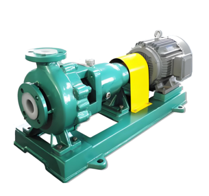
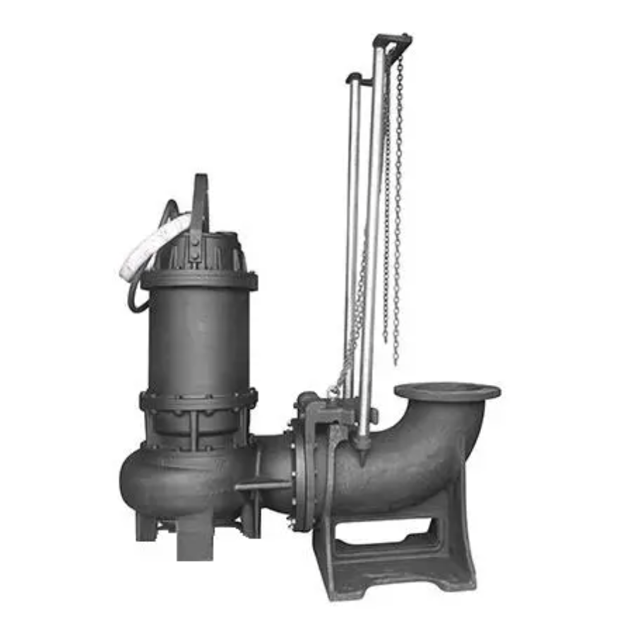
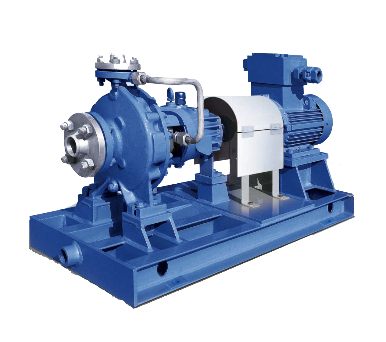
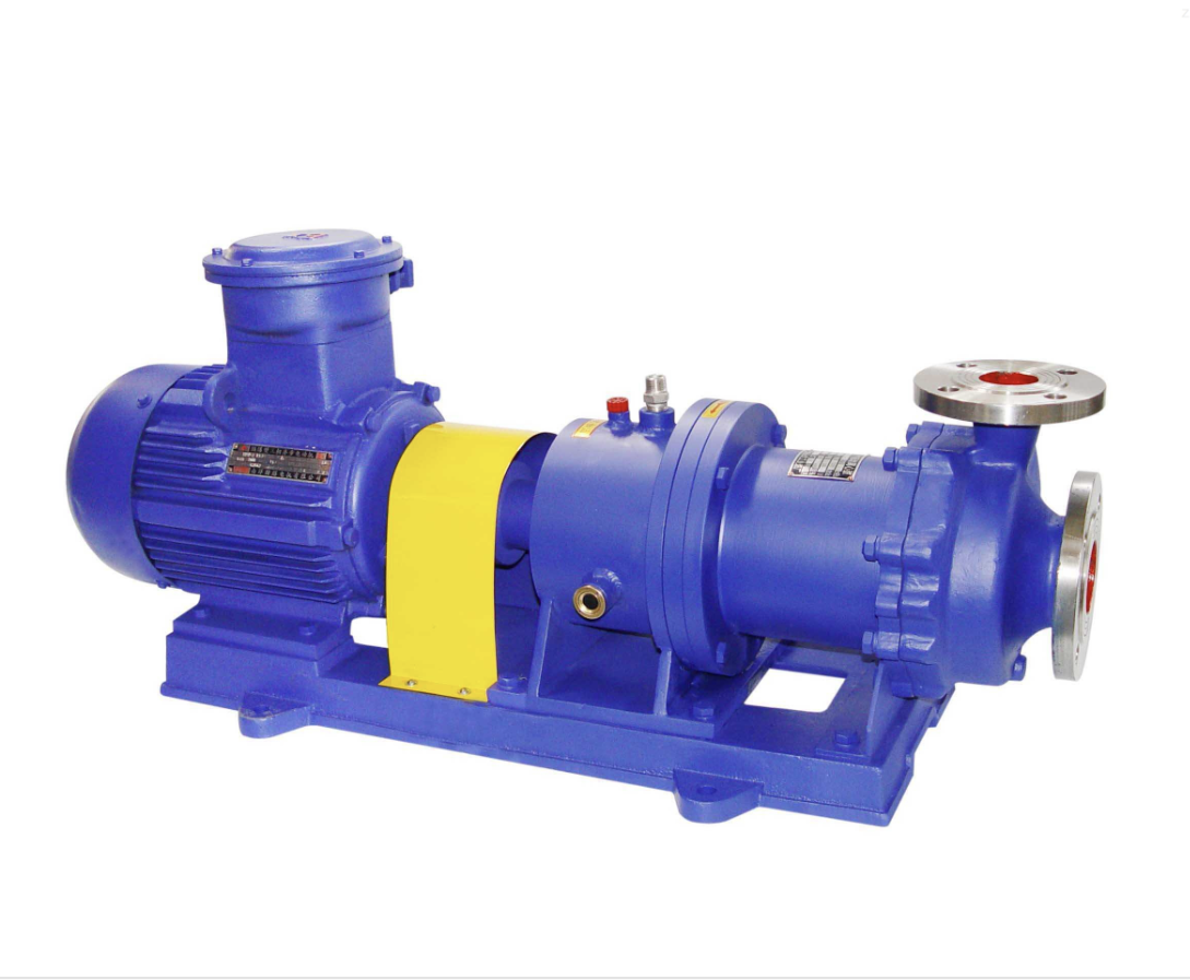
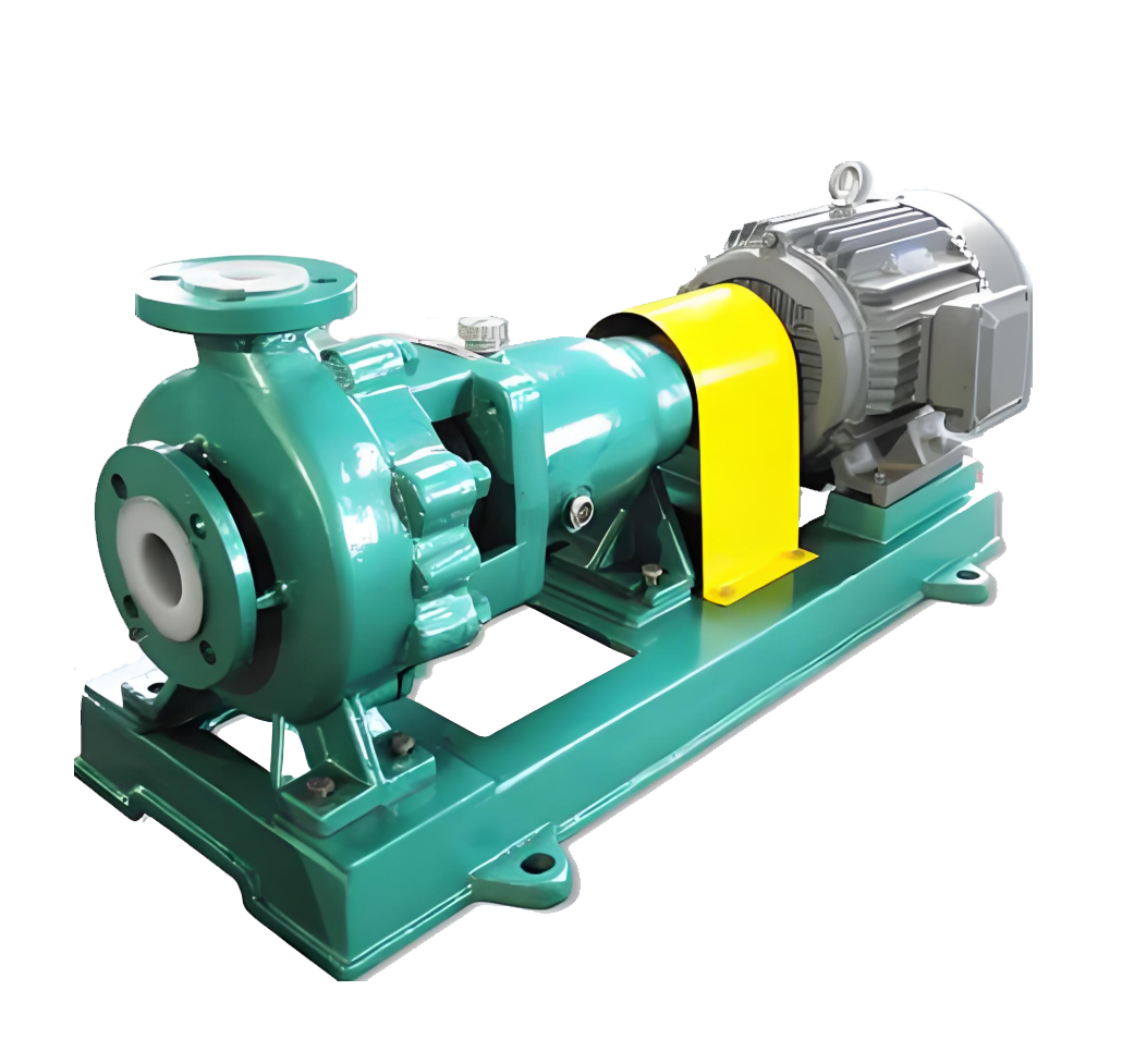
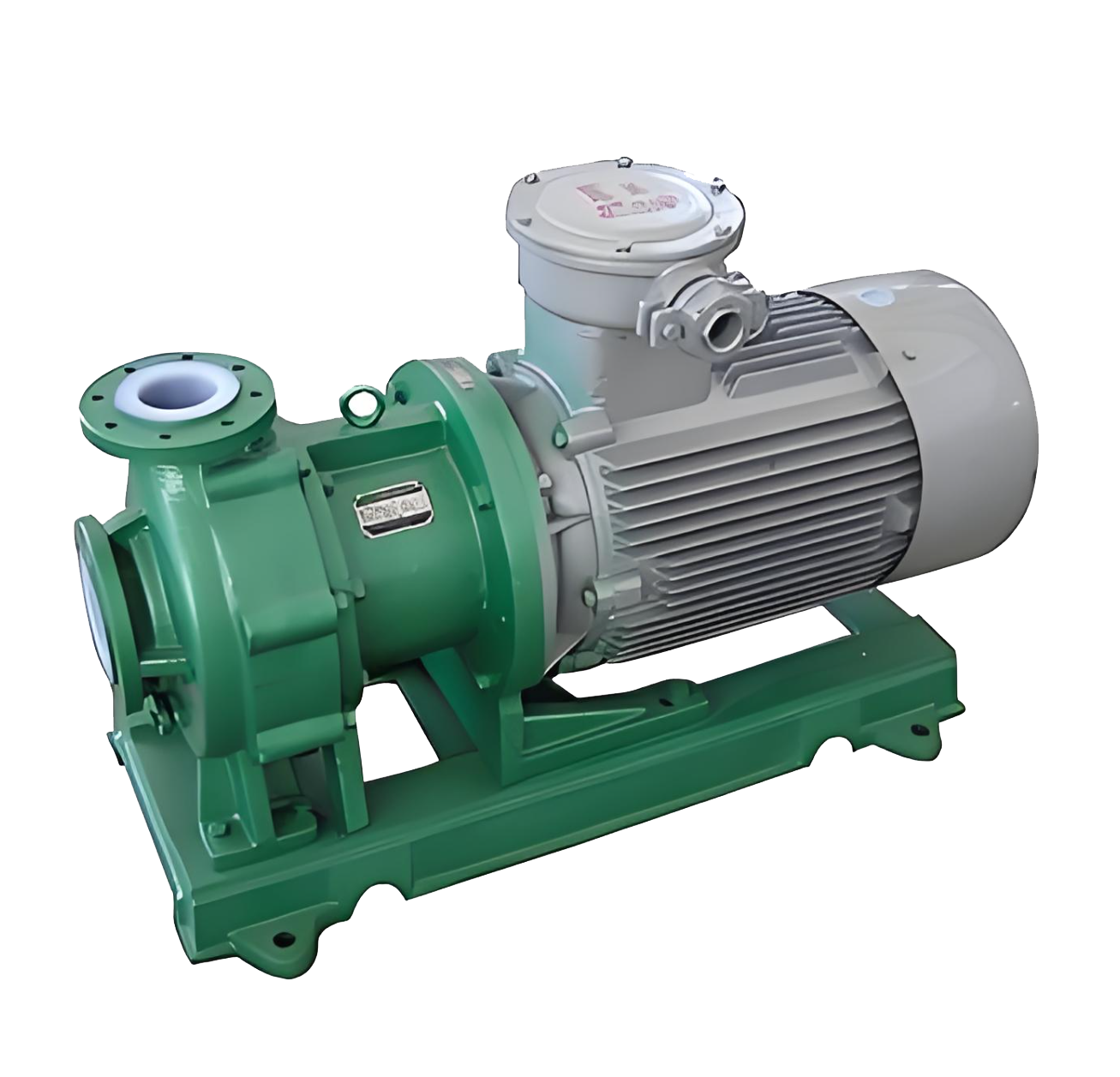
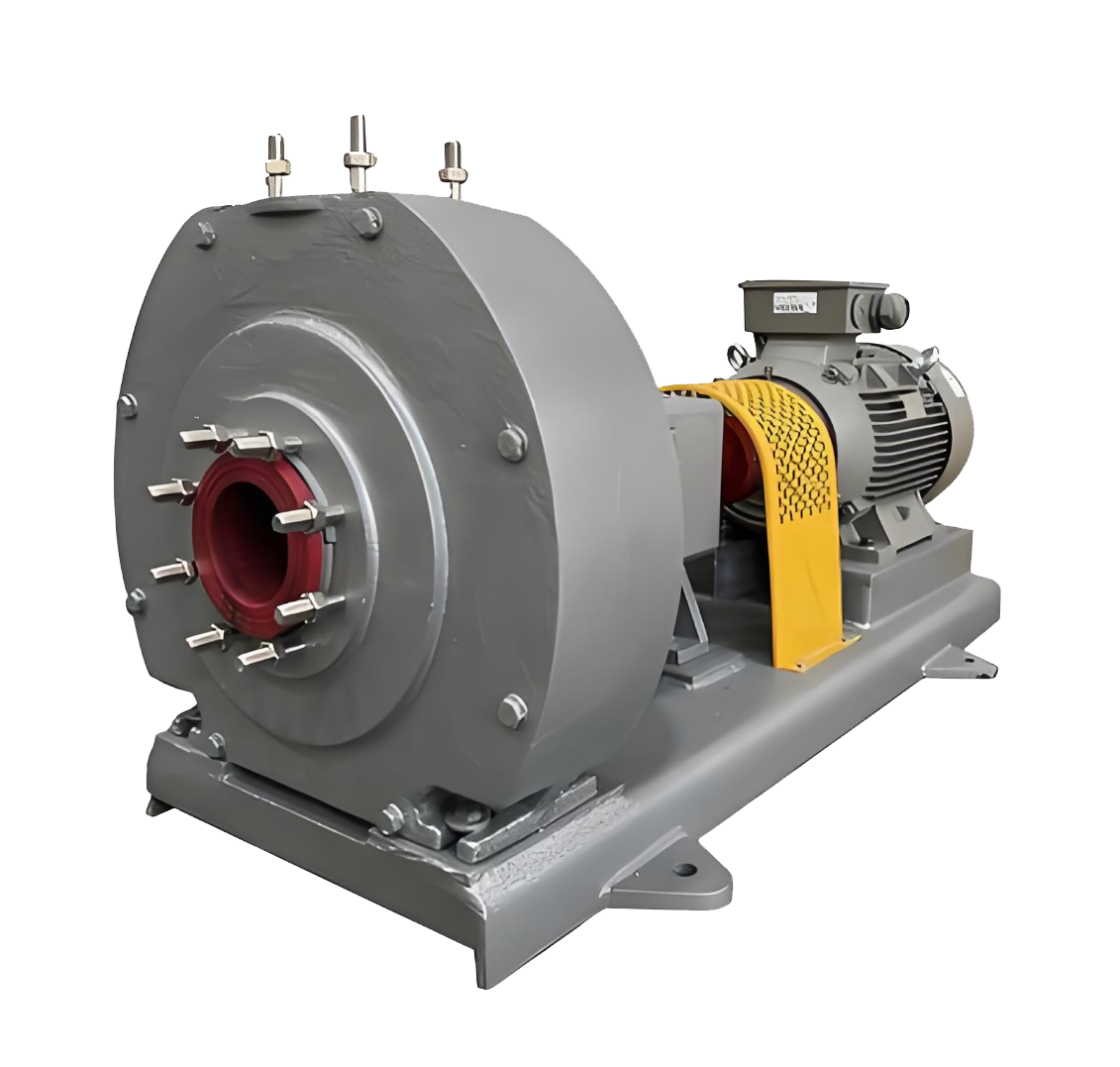
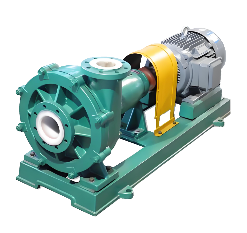
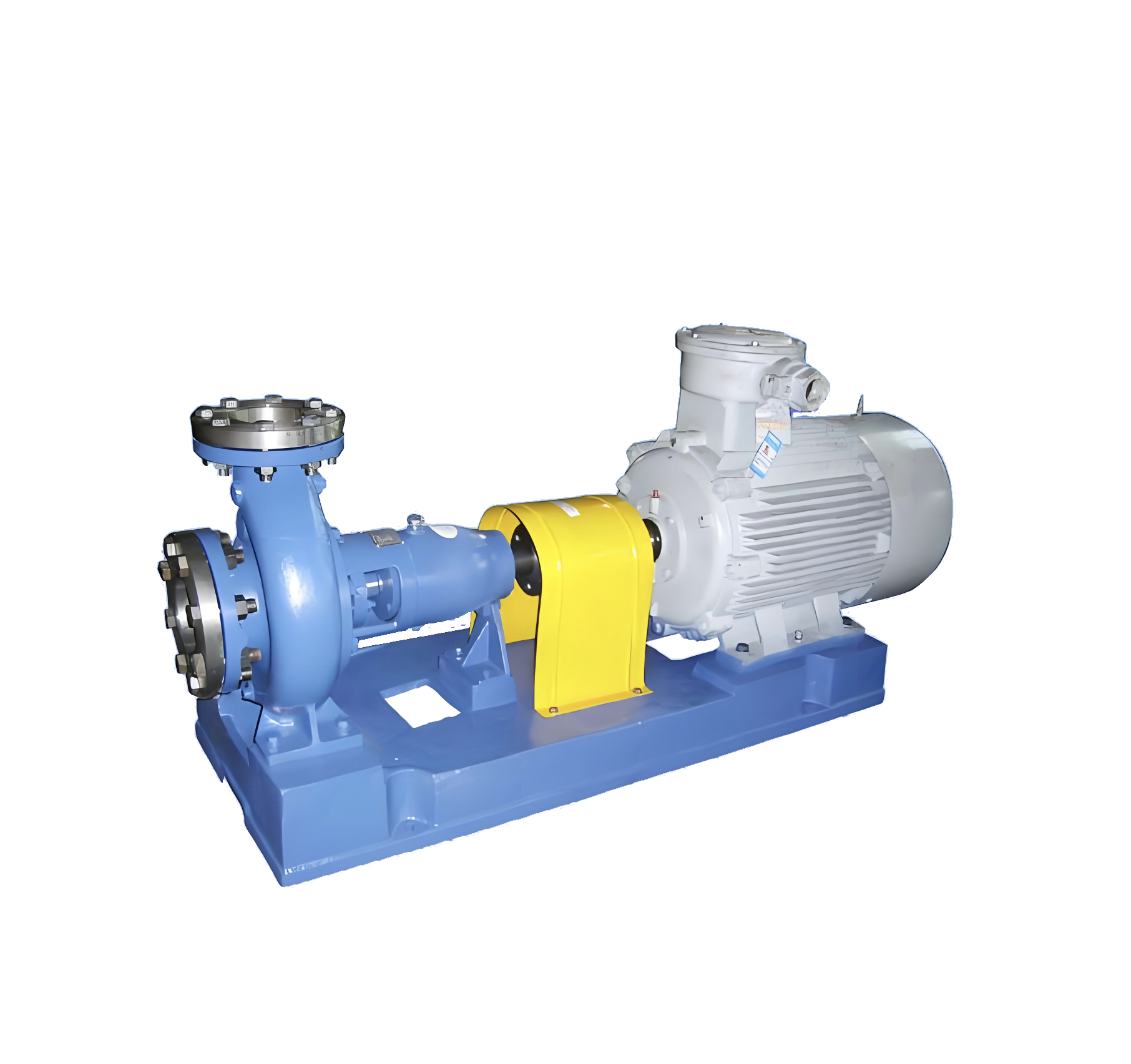
IHF-JNS High Temperature Fluoroplastic Centrifugal Pump Product Diagram
IHF-JNS series high temperature fluorine plastic pump is single-stage,single suction cantilevered centrifugal pump.pump body use meta shell lined with PFA and soluble fuorine alloy corosion resistant ceramic non-metalicmaterias.Impeler and pump cover use metal insert soluble PFA outsourcing and fluorine aloy molding.Thisproduct is designed reference to ISO2858 international standard,use built-in water cooled double end mechanical seal(Patent No:201420656053.4).Widely used in transport of solid content below 15%strong corrosive media、saturated solution of easy crystallization and strong akol:suifable for continuous operalion below 150℃ working temperature.Applcation industry:Manufacture of acid and akali、saturated electrolyte in non-ferrous pietalgmelting、desulfurizing and dust removinginenvironmental protection industry、ickin and adid re enerationin the steel industr.
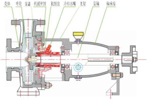
Structural diagram
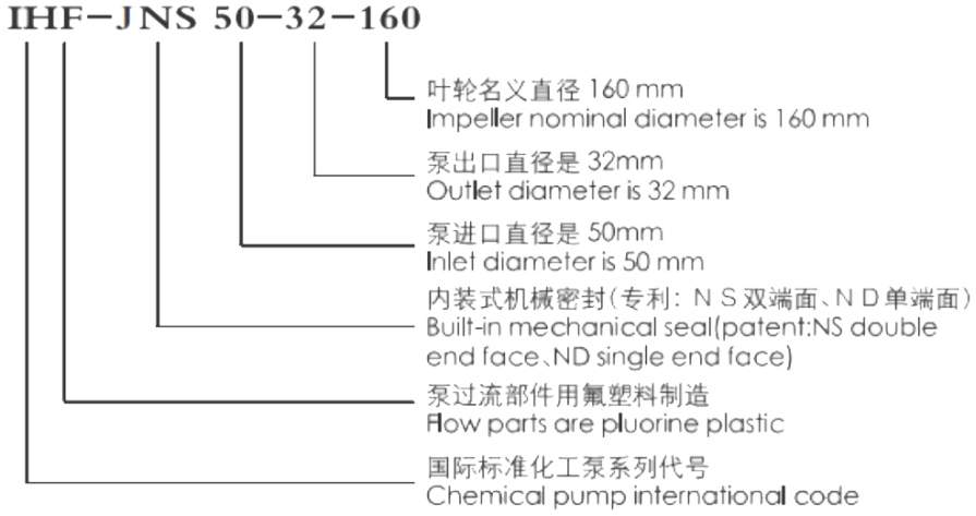
Model Meaning
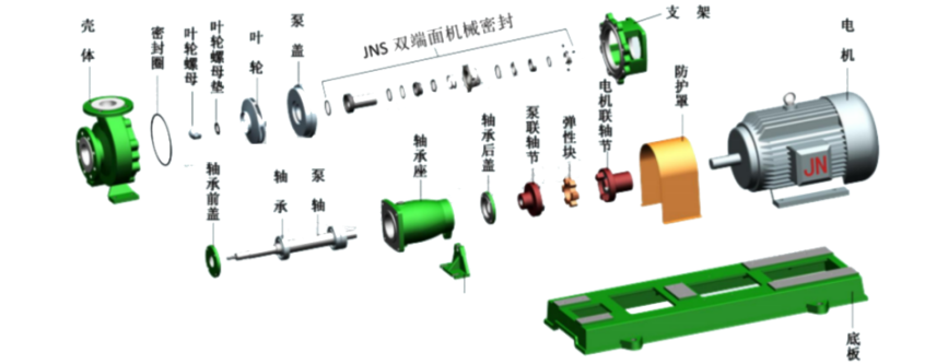
Split diagram

Model and Performance Parameter Table(n=2900r/min) bold font as the standard model
| 序号 | 型号(Model) | 转速(Rev)=2900r/min 介质密度(Medium density)=1000kg/m³ | |||||||
| 流量Flow (m³/h) | 扬程Pump head (m) | 效率η(%) | 进口Inlet (mm) | 出 口 Outlet (mm) | 汽蚀余量 NPSHr (m) | 电机功率 Power (kw) | 整机重量Weight (kg) | ||
| 1 | HF-JNS 32-25-125 | 2.5 | 22 | 26 | φ32 | φ20 | 3.0 | 1.5 | 85 |
| 3.6 | 20 | ||||||||
| 5 | 18 | ||||||||
| 2 | HF-JNS 32-20-160 | 2.5 | 33 | 20 | φ32 | φ20 | 3.0 | 2.2 | 90 |
| 3.6 | 32 | ||||||||
| 5 | 30 | ||||||||
| 3 | IHF-JNS 40-25-125 | 4 | 21 | 35 | 中40 | 中25 | 3.0 | 1.5 | 78 |
| 6.3 | 20 | ||||||||
| 7.5 | 18 | ||||||||
| 4 | HF-JNS 40-25-160 | 4 | 33 | 32 | φ40 | φ25 | 3.0 | 2.2 | 92 |
| 6.3 | 32 | ||||||||
| 7.5 | 28 | ||||||||
| 5 | HF-JNS 40-25-200 | 4 | 51 | 25 | φ40 | φ25 | 3.0 | 5.5 | 147 |
| 6.3 | 50 | ||||||||
| 7.5 | 47 | ||||||||
| 6 | HF-JNS 40-25-250 | 4 | 81 | 23 | φ40 | 中25 | 3.0 | 11 | 233 |
| 6.3 | 80 | ||||||||
| 7.5 | 78 | ||||||||
| 7 | HF-JNS 50-32-125 | 7 | 22 | 51 | φ50 | φ32 | 3.0 | 2.2 | 90 |
| 12.5 | 20 | ||||||||
| 15 | 16 | ||||||||
| 8 | HF-JNS 50-32-160 | 7 | 33 | 45 | φ50 | φ32 | 3.0 | 4 | 125 |
| 12.5 | 32 | ||||||||
| 15 | 30 | ||||||||
| 9 | HF-JNS 50-32-200 | 7 | 51 | 39 | φ50 | φ32 | 30 | 7.5 | 166 |
| 12.5 | 50 | ||||||||
| 15 | 47 | ||||||||
| 10 | HF-JNS 50-32-250 | 7 | 81 | 35 | φ50 | φ32 | 5.0 | 11 | 235 |
| 12.5 | 80 | ||||||||
| 15 | 77 | ||||||||
| 11 | HF-JNS 50-32-315 | 7 | 115 | 20 | φ50 | φ32 | 5.0 | 30 | 300 |
| 12.5 | 110 | ||||||||
| 15 | 105 | ||||||||
| 12 | HF-JNS 65-50-125 | 15 | 22 | 62 | φ65 | φ50 | 35 | 4 | 99 |
| 25 | 20 | ||||||||
| 35 | 18 | ||||||||
| 13 | HF-JNS 65-50-160 | 15 | 33 | 57 | φ65 | φ50 | 35 | 5.5 | 146 |
| 25 | 32 | ||||||||
| 35 | 28 | ||||||||
| 14 | IHF-JNS 65-40-200 | 15 | 51 | 52 | φ65 | φ40 | 3.5 | 11 | 214 |
| 25 | 50 | ||||||||
| 35 | 45 | ||||||||
| 15 | IHF-JNS 65-40-250 | 15 | 82 | 49 | 中65 | 中40 | 35 | 18.5 | 297 |
| 25 | 80 | ||||||||
| 35 | 72 | ||||||||
| 16 | HF-JNS 80-65-125 | 35 | 22 | 66 | φ80 | φ65 | 4.0 | 5.5 | 146 |
| 50 | 20 | ||||||||
| 60 | 18 | ||||||||
| 17 | HF-JNS 80-65-160 | 35 | 33 | 64 | φ80 | φ65 | 4.0 | 11 | 214 |
| 50 | 32 | ||||||||
| 60 | 27 | ||||||||
| 18 | IHF-JNS 80-50-200 | 35 | 52 | 63 | φ80 | φ50 | 4.0 | 15 | 230 |
| 50 | 50 | ||||||||
| 60 | 45 | ||||||||
| 19 | HF-JNS 80-50-250 | 35 | 82 | 57 | φ80 | φ50 | 4.5 | 30 | 393 |
| 50 | 80 | ||||||||
| 60 | 75 | ||||||||
continued Table
| 序号 | 型号(Model) | 转速(Rev)=2900r/min 介质密度(Medium density)=1000kg/m³ | |||||||
| 流量 Flow (m³/h) | 扬程Pump head(m) | 效率 η (%) | 进口 Inlet (mm) | 出 口 Outlet (mm) | 汽蚀余量 NPSHr(m) | 电机功率 Power(kw) | 整机重量 Weight (kg) | ||
| 20 | IHFJNS100-80-125 | 65 | 22 | 66 | φ100 | φ80 | 4.5 | 11 | 215 |
| 100 | 20 | ||||||||
| 110 | 18 | ||||||||
| 21 | IHF-JNS100-80-160 | 65 | 35 | 71 | φ100 | φ80 | 5.0 | 15 | 254 |
| 100 | 32 | ||||||||
| 120 | 26 | ||||||||
| 22 | IHF-JNS100-65-200 | 65 | 51 | 67 | φ100 | 中65 | 5.0 | 30 | 382 |
| 100 | 50 | ||||||||
| 120 | 43 | ||||||||
| 23 | IHF-JNS100-65-250 | 65 | 82 | 65 | φ100 | φ65 | 5.0 | 45 | 540 |
| 100 | 80 | ||||||||
| 120 | 65 | ||||||||
| 24 | IHF-JNS125-80-160 | 100 | 38 | 70 | φ125 | φ80 | 5.0 | 30 | 477 |
| 160 | 32 | ||||||||
| 180 | 26 | ||||||||
| 25 | IHF-JNS125-100-200 | 120 | 55 | 65 | 中125 | 中100 | 6.0 | 55 | 630 |
| 200 | 50 | ||||||||
| 220 | 45 | ||||||||
Model and Performance Parameter Table(n=1450r/min)
| 序号 | 型号(Model) | 转速(Rev)=1450r/min 介质密度(Medium density)=1000kg/m³ | |||||||
| 流量 Flow (m³/h) | 扬程Pump head (m) | 效率 η(%) | 进口 Inlet (mm) | 出 口 Outlet(mm) | 汽蚀余量 NPSHr (m) | 电机功率 Power (kw) | 整机重量 Weight (kg) | ||
| 1 | IHF-JNS40-25-125 | 2 | 5.5 | 32 | φ40 | φ25 | 3.0 | 0.55 | 70 |
| 3.2 | 5 | ||||||||
| 4 | 3 | ||||||||
| 2 | HF-JNS40-25-160 | 2 | 9 | 28 | φ40 | φ25 | 3.0 | 0.55 | 75 |
| 3.2 | 8 | ||||||||
| 4 | 6 | ||||||||
| 3 | IHF-JNS40-25-200 | 2 | 13 | 23 | φ40 | φ25 | 3.0 | 0.55 | 80 |
| 3.2 | 12.5 | ||||||||
| 4 | 10 | ||||||||
| 4 | HF-JNS40-25-250 | 2 | 20.5 | 20 | φ40 | φ25 | 2.0 | 1.5 | 85 |
| 3.2 | 20 | ||||||||
| 4 | 19.5 | ||||||||
| 5 | HF-JNS50-32-125 | 4 | 5.5 | 45 | 中50 | φ32 | 3.0 | 0.55 | 73 |
| 6.3 | 5 | ||||||||
| 8 | 3.5 | ||||||||
| 6 | IHF-JNS50-32-160 | 4 | 9 | 40 | φ50 | φ32 | 3.0 | 0.55 | 91 |
| 6.3 | 8 | ||||||||
| 8 | 6 | ||||||||
| 7 | IHF-JNS50-32-200 | 4 | 13 | 33 | φ50 | φ32 | 3.0 | 1.1 | 105 |
| 6.3 | 12.5 | ||||||||
| 8 | 10 | ||||||||
| 8 | IHF-JNS50-32-250 | 3.5 | 21 | 30 | φ50 | φ32 | 5.0 | 1.5 | 128 |
| 6.3 | 20 | ||||||||
| 7 | 18 | ||||||||
| 9 | IHF-JNS50-32-315 | 3.5 | 32.5 | 15 | 中50 | 中32 | 5.0 | 5.5 | 150 |
| 6.3 | 32 | ||||||||
| 9 | 30 | ||||||||
| 10 | IHF-JNS65-50-125 | 8 | 5.5 | 55 | φ65 | φ50 | 3.5 | 0.55 | 80 |
| 12.5 | 5 | ||||||||
| 15 | 3 | ||||||||
| 11 | IHF-JNS65-50-160 | 8 | 9 | 51 | φ65 | φ50 | 3.5 | 1.1 | 92 |
| 12.5 | 8 | ||||||||
| 15 | 6 | ||||||||
continued Table
| 序 号 | 型 号 ( M o d e l ) | 转速(Rev)=1450r/min 介质密度(Medium density)=100Okg/m³ | |||||||
| 流 量 Flow(m³/h) | 扬 程Pump head (m) | 效 率η(%) | 进 口 Inlet (mm) | 出 口 Outlet(mm) | 汽蚀余量 NPSHr (m) | 电机功率 Power (kw) | 整机重量Weight (kg) | ||
| 12 | IHF-JNS65-40-200 | 8 | 13 | 46 | φ65 | φ40 | 3.5 | 1.5 | 110 |
| 12.5 | 12.5 | ||||||||
| 15 | 10 | ||||||||
| 13 | IHF-JNS65-40-250 | 8 | 21 | 43 | 中65 | 中 4 0 | 3.5 | 3 | 140 |
| 12.5 | 20 | ||||||||
| 15 | 18 | ||||||||
| 14 | IHF-JNS80-65-125 | 16 | 5.5 | 64 | 中 8 0 | 中 6 5 | 4.0 | 1.1 | 110 |
| 25 | 5 | ||||||||
| 35 | 3 | ||||||||
| 15 | IHF-JNS80-65-160 | 16 | 9 | 62 | φ80 | φ65 | 4.0 | 1.5 | 110 |
| 25 | 8 | ||||||||
| 35 | 6 | ||||||||
| 16 | IHF-JNS80-50-200 | 16 | 13 | 57 | φ80 | φ50 | 4.0 | 2.2 | 120 |
| 25 | 12.5 | ||||||||
| 35 | 10 | ||||||||
| 17 | IHF-JNS80-50-250 | 16 | 21 | 53 | φ80 | φ50 | 4.5 | 4 | 140 |
| 25 | 20 | ||||||||
| 35 | 18 | ||||||||
| 18 | IHF-JNS80-50-315 | 20 | 34 | 40 | φ80 | φ50 | 5.0 | 7.5 | 220 |
| 25 | 32 | ||||||||
| 35 | 29 | ||||||||
| 19 | IHF-JNS100-80-125 | 35 | 5.5 | 64 | φ100 | φ80 | 4.5 | 1.5 | 130 |
| 50 | 5 | ||||||||
| 60 | 3 | ||||||||
| 20 | IHF-JNS100-80-160 | 35 | 8.5 | 68 | 中 1 0 0 | φ80 | 5.0 | 2.2 | 140 |
| 50 | 8 | ||||||||
| 60 | 6 | ||||||||
| 21 | IHF-JNS100-65-200 | 35 | 13 | 64 | φ100 | φ65 | 5.0 | 4 | 320 |
| 50 | 12.5 | ||||||||
| 60 | 10 | ||||||||
| 22 | HF-JNS100-65-250 | 32.5 | 20.5 | 62 | φ100 | φ65 | 5.0 | 7.5 | 350 |
| 50 | 20 | ||||||||
| 60 | 16.3 | ||||||||
| 23 | IHF-JNS125-80-160 | 50 | 10 | 69 | φ125 | φ80 | 5.0 | 4 | 300 |
| 80 | 8 | ||||||||
| 90 | 6 | ||||||||
| 24 | IHF-JNS125-100-200 | 65 | 13 | 64 | φ125 | φ100 | 6.0 | 7.5 | 375 |
| 100 | 12.5 | ||||||||
| 120 | 10 | ||||||||
| 25 | IHF-JNS125-100-250 | 65 | 21 | 63 | φ125 | φ100 | 6.0 | 15 | 386 |
| 100 | 20 | ||||||||
| 120 | 18 | ||||||||
| 26 | HF-JNS125-100-315 | 65 | 36 | 60 | φ125 | 中 1 0 0 | 3.0 | 18.5 | 480 |
| 100 | 32 | ||||||||
| 120 | 30 | ||||||||
| 27 | IHF-JNS150-125-250 | 130 | 22 | 67 | 中 1 5 0 | 中 1 2 5 | 7.0 | 22 | 500 |
| 200 | 20 | ||||||||
| 240 | 18 | ||||||||
| 28 | IHF-JNS150-125-315 | 120 | 36 | 65 | 中 1 5 0 | 中 1 2 5 | 7.0 | 45 | 660 |
| 200 | 32 | ||||||||
| 240 | 30 | ||||||||
| 29 | IHF-JNS150-125-400 | 120 | 55 | 61 | 中 1 5 0 | 中 1 2 5 | 7.0 | 75 | 860 |
| 200 | 50 | ||||||||
| 240 | 46 | ||||||||
| 30 | IHF-JNS200-150-250 | 240 | 22 | 69 | 中 2 0 0 | 中 1 5 0 | 7.5 | 45 | 680 |
| 400 | 20 | ||||||||
| 480 | 17 | ||||||||
| 31 | IHF-JNS200-150-315 | 240 | 36 | 68 | φ200 | φ150 | 7.5 | 75 | 940 |
| 400 | 32 | ||||||||
| 480 | 29 | ||||||||
| 32 | IHF-JNS200-150-400 | 240 | 55 | 63 | φ200 | φ150 | 7.5 | 110 | 1160 |
| 400 | 50 | ||||||||
| 480 | 46 | ||||||||
| 33 | IHF-JNS250-200-250 | 500 | 24 | 70 | φ250 | 中 2 0 0 | 7.5 | 75 | 1100 |
| 650 | 20 | ||||||||
| 750 | 15 | ||||||||
| 34 | IHF-JNS250-200-315 | 500 | 36 | 69 | 中 2 5 0 | φ200 | 7.5 | 110 | 1480 |
| 650 | 32 | ||||||||
| 750 | 27 | ||||||||
| 35 | HF-JNS300-250-315 | 800 | 36 | 72 | 中 3 0 0 | φ250 | 8 | 160 | 2160 |
| 1000 | 32 | ||||||||
| 1150 | 27 | ||||||||
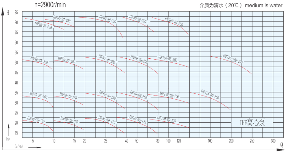
performance curve(n=2900r/min)
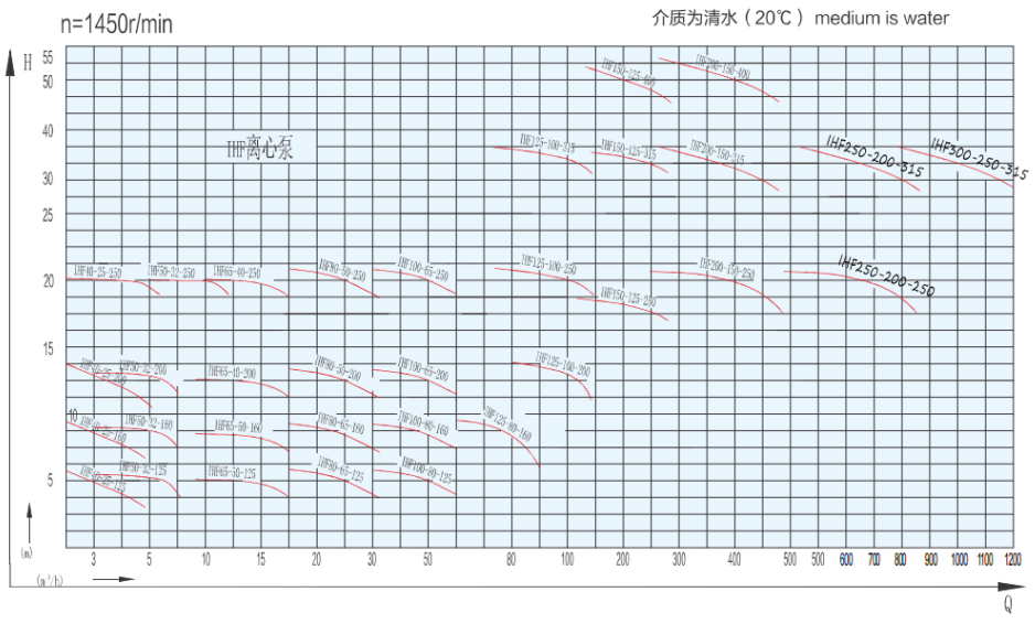
performance curve(n=1450r/min)
Outline dimension diagram
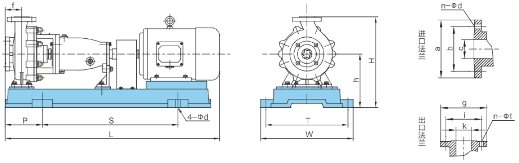
Outline dimension table *表中尺寸仅供参考,公司保留更改的权利,以单页具体型号安装尺寸为准。
| 序 号 | 系列型号 Model | 外 型 安 装 尺 寸Outside and installing size | 进口法兰尺寸Inlet flange size | 出口法兰尺寸Outlet flange size | ||||||||||||||
| L | S | P | f | W | T | H | h | D | C | a | b | n-φd | k | g | i | n-中t | ||
| 1 | HF40-25-125 | 800 | 485 | 155 | 80 | 362 | 320 | 360 | 197 | 16 | 40 | 150 | 110 | 4-417.5 | 25 | 115 | 85 | 4-φ13.5 |
| 2 | IHF40-25-160 | 800 | 485 | 155 | 80 | 362 | 320 | 360 | 197 | 16 | 40 | 150 | 110 | 4-417.5 | 25 | 115 | 85 | 4-φ13.5 |
| 3 | HF40-25-200 | 1025 | 650 | 160 | 80 | 450 | 385 | 440 | 260 | 24 | 40 | 150 | 110 | 4-417.5 | 25 | 115 | 85 | 4-p13.5 |
| 4 | HF40-25-250 | 1224 | 740 | 208 | 100 | 490 | 440 | 485 | 260 | 24 | 40 | 150 | 110 | 4-417.5 | 25 | 115 | 85 | 4-p13.5 |
| 5 | HF50-32-125 | 950 | 605 | 155 | 80 | 395 | 335 | 352 | 212 | 24 | 50 | 165 | 125 | 4-φ17.5 | 32 | 140 | 100 | 4-中17.5 |
| 6 | HF50-32-160 | 950 | 605 | 155 | 80 | 395 | 335 | 392 | 232 | 24 | 50 | 165 | 125 | 4-417.5 | 32 | 140 | 100 | 4-中17.5 |
| 7 | HF50-32-200 | 1075 | 650 | 160 | 80 | 450 | 385 | 440 | 260 | 24 | 50 | 165 | 125 | 4-φ17.5 | 32 | 140 | 100 | 4-中17.5 |
| 8 | HF50-32-250 | 1224 | 740 | 208 | 100 | 490 | 440 | 485 | 260 | 24 | 50 | 165 | 125 | 4-417.5 | 32 | 140 | 100 | 4-417.5 |
| 9 | HF65-50-125 | 995 | 600 | 160 | 80 | 395 | 335 | 352 | 212 | 24 | 65 | 185 | 145 | 4-φ17.5 | 50 | 165 | 125 | 4-中17.5 |
| 10 | HF65-50-160 | 1075 | 650 | 155 | 80 | 435 | 385 | 392 | 232 | 24 | 65 | 185 | 145 | 4-417.5 | 50 | 165 | 125 | 4-417.5 |
| 11 | HF65-40-200 | 1240 | 735 | 205 | 100 | 500 | 425 | 440 | 260 | 24 | 65 | 185 | 145 | 4-φ17.5 | 40 | 150 | 110 | 4-φ17.5 |
| 12 | HF65-40-250 | 1314 | 850 | 200 | 100 | 490 | 435 | 505 | 280 | 24 | 65 | 185 | 145 | 4-φ17.5 | 40 | 150 | 110 | 4-417.5 |
| 13 | HF80-65-125 | 1095 | 650 | 185 | 100 | 450 | 385 | 392 | 232 | 24 | 80 | 200 | 160 | 8-φ17.5 | 65 | 185 | 145 | 4-中17.5 |
| 14 | HF80-65-160 | 1240 | 740 | 205 | 100 | 500 | 435 | 440 | 260 | 24 | 80 | 200 | 160 | 8-φ17.5 | 65 | 185 | 145 | 4- 17.5 |
| 15 | HF80-50-200 | 1240 | 740 | 205 | 100 | 500 | 435 | 460 | 260 | 24 | 80 | 200 | 160 | 8-417.5 | 50 | 165 | 125 | 4-417.5 |
| 16 | HF80-50-250 | 1522 | 945 | 265 | 125 | 600 | 535 | 505 | 280 | 24 | 80 | 200 | 160 | 8-φ17.5 | 50 | 165 | 125 | 4- 17.5 |
| 17 | HF100-80-125 | 1230 | 740 | 220 | 100 | 500 | 435 | 440 | 260 | 24 | 100 | 220 | 180 | 8-17.5 | 80 | 200 | 160 | 8-。17.5 |
| 18 | HF100-80-160 | 1335 | 850 | 200 | 100 | 500 | 435 | 460 | 260 | 24 | 100 | 220 | 180 | 8-φ17.5 | 80 | 200 | 160 | 8-。17.5 |
| 19 | HF100-65-200 | 1543 | 945 | 240 | 100 | 610 | 535 | 520 | 300 | 24 | 100 | 220 | 180 | 8-φ17.5 | 65 | 185 | 145 | 4-中17.5 |
| 20 | HF100-65-250 | 1640 | 940 | 260 | 125 | 600 | 550 | 575 | 325 | 28 | 100 | 220 | 180 | 8-φ17.5 | 65 | 185 | 145 | 4- 17.5 |
| 21 | HF125-80-160 | 1543 | 945 | 260 | 125 | 600 | 535 | 520 | 300 | 24 | 125 | 250 | 210 | 8-。17.5 | 80 | 200 | 160 | 8-M16 |
| 22 | HF125-100-200 | 1714 | 1060 | 300 | 125 | 660 | 600 | 695 | 410 | 28 | 125 | 250 | 210 | 8-M16 | 100 | 220 | 180 | 8-M16 |
| 23 | HF125-100-250 | 1395 | 940 | 260 | 140 | 540 | 490 | 605 | 325 | 24 | 125 | 250 | 210 | 8-417.5 | 100 | 220 | 180 | 8-。17.5 |
| 24 | HF125-100-315 | 1520 | 940 | 260 | 140 | 540 | 490 | 665 | 350 | 28 | 125 | 250 | 210 | 8-φ17.5 | 100 | 220 | 180 | 8-917.5 |
| 25 | HF150-125-250 | 1540 | 940 | 260 | 140 | 540 | 490 | 705 | 350 | 24 | 150 | 285 | 240 | 8-622 | 125 | 250 | 210 | 8-φ17.5 |
| 26 | HF150-125-315 | 1685 | 940 | 265 | 140 | 620 | 550 | 795 | 440 | 28 | 150 | 285 | 240 | 8-o22 | 125 | 250 | 210 | 8-917.5 |
| 27 | HF150-125-400 | 1840 | 1060 | 300 | 140 | 670 | 600 | 875 | 475 | 28 | 150 | 285 | 240 | 8-622 | 125 | 250 | 210 | 8-φ17.5 |
| 28 | HF200-150-250 | 1674 | 940 | 285 | 160 | 620 | 550 | 440 | 815 | 25 | 200 | 340 | 295 | 12-φ23 | 150 | 285 | 240 | 8-φ22 |
| 29 | HF200-150-315 | 1890 | 1060 | 320 | 160 | 660 | 600 | 875 | 475 | 28 | 200 | 340 | 295 | 12-φ23 | 150 | 285 | 240 | 8-φ22 |
Schematic and Requirements for Common Devices of Centrifugal Pumps
Working condition of suction bottom valve:
The flow area of the bottom valve should be greater than the cross-sectional area of the inlet pipeline;
2. Before starting, it is necessary to fill the pump outlet with liquid;
3. The suction height at the lowest liquid level should meet the requirements of pump cavitation allowance and device cavitation allowance;
4. Set a lower limit liquid level sensor to prevent damage caused by pump emptying and dry grinding.
Siphon bucket suction condition:
Before starting, the siphon bucket must be filled with liquid to ensure that all pipe fittings in front of the pump inlet flange are sealed reliably and leak free:
The suction height of the cavitation allowance of the two devices is from the highest point to the lowest liquid level of the inlet pipeline of the siphon bucket:
3. Siphon bucket volume=6-8 times the volume of the pipeline in front of the bucket x medium density: 4. Set a lower limit liquid level sensor to prevent damage caused by pump emptying and dry grinding:
5. Valves should be installed for easy maintenance when importing:
6. It is recommended that the height/diameter of the siphon bucket be greater than 1.5 times
Backflow condition:
1. Valves should be installed for easy maintenance when importing;
Set a lower limit liquid level sensor to prevent damage caused by pump emptying and dry grinding;
3. This device is the most ideal suction condition, and it is recommended to use it as much as possible if conditions permit.
Backup condition:
1. Valves must be installed at the inlet of both pumps, and the backup pump valve should be closed when one is in operation;
2. The connection of imported shared pipelines must have a curved transition, and the pipeline area should be bolded according to the number of parallel connections;
3. Set a lower limit liquid level sensor to prevent damage caused by pump emptying and dry grinding.
① Electric control box ② outlet valve ③ inlet valve ④ liquid level sensor on the inlet pipeline and lower liquid level sensor
All pump outlets must be equipped with valves to regulate the pump's operation within the rated flow range. It is strictly prohibited to use inlet valves to regulate flow!
The above device requirements are applicable to IHF, CQB, FSB, FMB, IH, CQ series centrifugal pumps.
- Sales hotline:
+86 21 5640 2009 - Pump customer service:
+86 138 1691 3072 - Valve customer service:
+86 1381 6913 072 - E-mail:
my1pv@1bengfa.com

COPYRIGHT © ShangHai Meiyan Yi Pump & Valve Co.,LTD. Main Business:Pump、Valve
沪ICP备2026024063号-12
![]()